The largest quantity of generated greenhouse gas is carbon dioxide. Electricity generation is responsible for 42.5% of global CO2 emissions, of which 73% are attributed to coal-fired power plants. Technologies are being developed whereby carbon dioxide emissions are collected and either reused or stored instead of being released into the environment. This process is known as carbon capture, utilisation, and storage (CCUS), sometimes known as carbon capture, utilisation, and sequestration [1]. Recent news headlines highlight the magnitude of its future potential use. Aug 15th 2023, Carbon Engineering Ltd, a Canadian start-up, was bought by oil producer Occidental Petroleum Corp for $1.1 billion. Yet one must beware of the mixed message to oil companies. Oil capture should not become an invitation to abandon our fight against fossil fuels.
What is carbon sequestration?
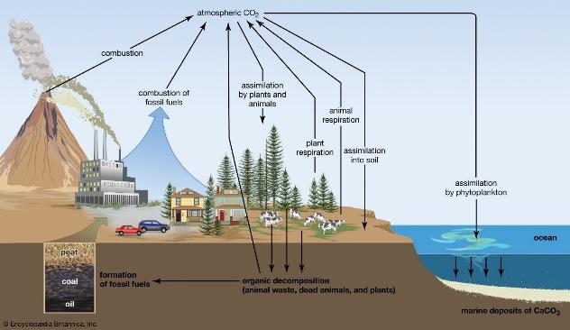
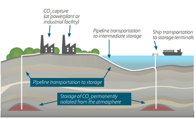
Figure 1: Atmospheric Carbon Capture, Utilisation and Storage
The technique of removing and retaining carbon dioxide from the atmosphere is known as carbon sequestration [2]. It is one way to lessen atmospheric carbon dioxide in the effort to slow down the rate of global warming. Deep saline reserves, coal layers that cannot be mined, and oil and gas reservoirs are just a few of the geologic formations that can store carbon dioxide. There are two basic methods for storing CO2, underground storage and mineral preservation. The problem of acidification of the oceans, which is partly brought on by the excess of CO2 currently present in the atmosphere and seas, can only be amplified by deep ocean storage therefore it should be avoided. Alternative storage locations being pursued are underground storage or geological formations. The US Gulf Coast and the North Sea are believed to offer significant underground storage capacity. According to the Intergovernmental Panel on Climate Change (IPCC), CO2 might be held for thousands of years at optimised geological storage sites, with over 99% Injected CO2 remaining even after a thousand years.
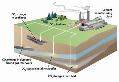
Figure 3: CO2 Underground Storage Types
Quantifying carbon sequestration
CO2 is captured at the point of emission, transported, and then stored or buried in a suitably deep underground site. Carbon sequestration may also refer to the direct or indirect capture of CO2 from the atmosphere. In 2010, CO2 emissions from fossil fuels amounted to 32 Gigatonnes. These emissions are produced by fixed emission sources including power plants, cement plants, and distilleries as well as industrial activities. The previous 40 years created almost 50% of the total manmade CO2 emissions between the years of 1750 and 2010 [3].
The injection of CO2 into a subterranean or underground structure for secure and long-term storage is known as geologic storage. Five different subterranean formations are being looked at by the U.S. Department of Energy for geological carbon storage: coal seams, saline formations, basalt formations, oil and natural gas reservoirs, and organic-rich shales [4].
Large sources of CO2, namely coal-fired power stations, which emit 950 grams for every kilowatt-hour of electricity they generate, gas-fired power plants (350g) industrial plants, and other industrial operations, can collect at the source. It is also possible to capture from the atmosphere. In the USA, tax credits are made available to capture and permanently store CO2, of $85/tonne if at the source or $180/tonne if from ambient air. New facilities are making use of such financial incentives, but retrofitting existing refineries, ammonia or other petrochemical facilities, is still rare.
Transportation and Enhanced Oil Recovery
Transporting CO2 to appropriate storage locations after collection is challenging. The fastest method of transportation is to pump it through pipes, which is a practical and stable process. For small-scale applications, CO2 may also be transported using ships and road tankers.
In the United States, CO2 is transported through 5800 km of pipes to oil wells where it is administered to facilitate in the extraction of additional oil recovery. The name of this procedure is enhanced oil recovery, or EOR [5]. Billion-cell reservoir simulation models are used to help manage carbon dioxide. The models predict CO2‘s behaviour when injected into either saline aquifers of depleted oil or gas reservoirs, and over the decades that will follow its sequestration.
Methods of storage: structural, residual and solubility trapping
Underground supercritical fluid storage is possible for CO2. The critical pressure and temperature for CO2 are 72.9 atmospheric pressure and 31.1°C respectively [4]. Supercritical CO2 is classified as the CO2 at these temperatures and pressures. The CO2 exhibits both gaseous and liquid-like characteristics at these pressures and temperatures. It possesses volatility like a gas and is very thick like a liquid. The principal benefit of keeping CO2 in a supercritical state for storage is that much less space is needed than if it were to be kept at normal room pressure settings. The ambient temperature and fluid pressure are above the critical threshold of CO2 for the majority of sites on Earth at levels beneath 800 meters [4]. This indicates that considering the current temperatures and pressures, CO2 deposited at this depth, or deeper still, will continue to be in the supercritical state.
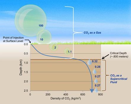
Figure 4: Pressure Effects on CO2 for Underground Storage [4]
The CO2 stays underground in the area where it is injected, a process known as trapping. The four basic processes that keep the injected CO2 trapped underground is structural trapping, residual trapping, solubility trapping and mineral trapping.
The process through which the most CO2 is physically trapped in the bedrock is known as structural entrapment. The CO2 injection site's internal and external sedimentary layers and faults serve as enclosures to stop CO2 from leaving the storage formation by acting as barriers. Supercritical CO2 is more volatile than other fluids in the nearby pore region after it has been injected. Due to this, the CO2 will rise through the permeable rocks until it approaches an impervious layer of seal rock where it gets trapped. Illustration of two structural trapping cases is shown in the following figure. The CO2 is shown in the following figure (top) which is constrained by an arch, prohibiting transverse or vertical migration. The figure (bottom) demonstrates how a fault towards the right of the CO2 and the seal rock above it both prohibit CO2 from travelling upward.
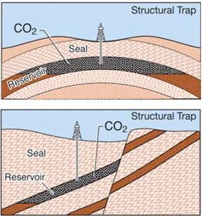
Figure 5: Structural Trapping [4]
Residual trapping is another process that occurs in entrapment which refers to the amount of CO2 that is held in place when the CO2 plume travels through the rock and becomes absorbed into the porous structure between the rock particles. Porous rock acts as a stiff sponge. When supercritical CO2 is introduced into the deposit, it pushes through the permeable rocks and replaces the pre-existing fluids. Low concentrations of CO2 get lost along the way as isolated or leftover droplets in the micropores, which are basically stationary, in a similar way to when liquid remains in a sponge. The following illustration shows the concentrations of CO2 that are still trapped in the porous channel between the rock particles as CO2 proceeds to the right via the cracks present in the rock.
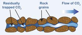
Figure 6: Residual Trapping [4]
Using a process known as solubility trapping, some of the injected CO2 will disintegrate into the brine water that is already existing in the rock's porous channel. The following figure illustrates the interaction between CO2 and brine water that causes solubility entrapment. Some of the CO2 molecules disintegrate into the brine water at the junction of the CO2 /brine water in the porous structure of the rock. Some of the dissolved CO2 subsequently becomes HCO3- when it mixes with accessible hydrogen atoms.
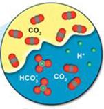
Figure 7: Solubility Trapping [4]
When the dissolved CO2 in the rock's brine water combines with the minerals present in the rock, it might lead to a phenomenon known as mineral entrapment. The weak carbonic acid (H2CO3) that results from CO2 dissolution in water ultimately transforms into bicarbonate HCO3-. This weak acid could interact over time with the elements in the neighbouring rocks to produce solid carbonate minerals, retaining and preserving some of the injected CO2 indefinitely. The figure illustrates how the absorbed CO2 in the brine water interacts with the surface of a rock fragment to produce minerals. The mineral MgCO3 is created on the layer of the rock grain when the magnesium reacts with the CO3 in the water.
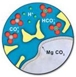
Figure 8: Mineral Trapping [4]
Carbon eating microbes, the future of carbon capture?
Nature’s evolutionary response to environmental changes has also inspired microbiologists to study a different method of carbon capture. Cyanobacteria are bacteria which have evolved, in certain environments rich in CO2, to utilise it to produce energy through photosynthesis. In September 2022, a new strain was recently identified off the cost of a volcanic island near Sicily, where hydrothermal vents, rich in CO2, are present in shallow waters which let sun-rays through. This has been the perfect environment for microbes to develop that uses photosynthesis through CO2 consumption. The breakthrough is in the speed at which this particular microbe strain consumes CO2. Dr Tierney, a data scientist focusing on microbiology at Weill Cornell Medical College and Harvard Medical School, has been leading the project for US biotechnology company Seed Health. Their research into more efficient strains still has taken them to heavily carbonated springs of Colorado/s Rocky Mountains, and they are creating a DNA database of the most efficient strains. An additional benefit of the process of carbon capture by microbes is the resulting biomass, which could be utilised as energy and tuned into biofuel, fertiliser, animal feed. Moreover, the cost of carbon capture by microbes is likely to be far less than that of air carbon capture. Lanzatech in the US and CyanoCapture in the UK have started to use CO2 eating microbes to produce energy.
Is carbon sequestration the penultimate solution?
The efficiency of the CCS technology, still in its infancy, remains to be proven over time. Moreover, the quantities of carbon it can tackle are still ill defined. Some environmentalists are therefore critical of the increasing government funding towards CCS at the expense of other environmental actions. In the US and UK environmentalist groups have accused governments of supporting carbon capture as the holy grail, as an alternative to the war against fossil fuel. Diminishing our dependence on fossil fuels and cutting emissions is costly and a difficult battle at a time of high inflation, but one with definite long-term benefits to the environment. Oil companies should not be given mixed messages that fossil fuels are now more acceptable because we can capture and store the carbon they release. Phasing out fossil fuels and carbon capture complement each other and should be given equal priority. As per Dr Tierney’s words, they should “work in concert”.
References
[1] Energy.gov, “Carbon Capture, Utilization & Storage | Department of Energy,” 2022. https://www.energy.gov/carbon-capture-utilization-storage (accessed Oct. 02, 2022).
[2] USGS, “What is carbon sequestration? | U.S. Geological Survey,” 2022. https://www.usgs.gov/faqs/what-carbon-sequestration (accessed Oct. 02, 2022).
[3] O. Edenhofer et al., “Summary for Policymakers,” Mitigation of Climate Change, 2014, Accessed: Oct. 02, 2022. [Online]. Available: https://www.ipcc.ch/site/assets/uploads/2018/02/ipcc_wg3_ar5_summary-for-policymakers.pdf
[4] National Energy Technology Laboratory, “Carbon Storage FAQs | netl.doe.gov,” 2022. https://netl.doe.gov/carbon-management/carbon-storage/faqs/carbon-storage-faqs (accessed Oct. 02, 2022).
[5] J. van Straelen, F. Geuzebroek, N. Goodchild, G. Protopapas, and L. Mahony, “CO2 capture for refineries, a practical approach,” Energy Procedia, vol. 1, no. 1, pp. 179–185, Feb. 2009, doi: 10.1016/J.EGYPRO.2009.01.026.


.svg)


.png)

.svg)